COVO KNOWLEDGE
Press brake dies for data center enclosures: complete 2026 guide
Published:
Updated:
Select press brake dies for data center enclosures by fit, not labels. Check flange support, radius, clamping interface and loads before releasing your setup.
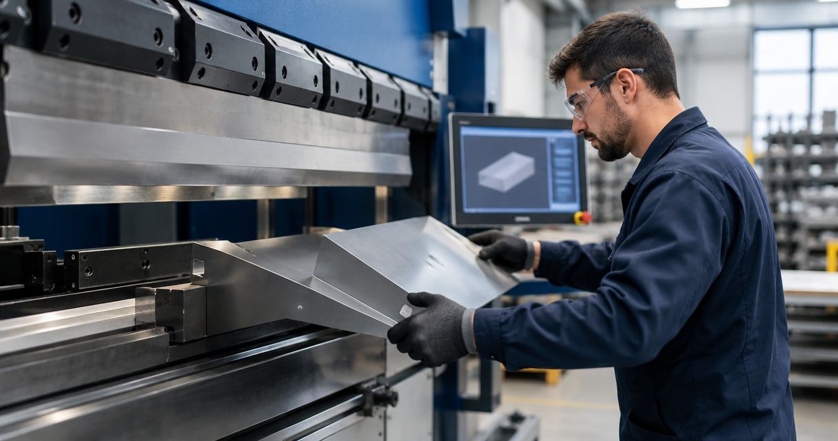
Data center enclosure die selection is the specification of press brake dies and matched punches to produce sheet-metal housings with the required fit, geometry and finish. This 2026 guide covers press brake dies for data center enclosures, where return flanges, ventilation cutouts, door interfaces and bend sequence must be checked together—not as separate tooling decisions.
- Select press brake dies for data center enclosures from the finished-part drawing, material specification and machine interface.
- COVO suits enclosure fabricators needing custom press brake tooling reviewed against part geometry and machine specifications.
- Check V-opening, flange support, bend radius and rated load together; none establishes suitability alone.
- Verify sectional tooling clearance throughout the bend sequence, including finished-part removal.
Why die selection matters for enclosure fabricators
An enclosure bend affects more than its local angle. A flange positions adjoining panels, a return changes tool clearance, and a bend near a cutout changes how the sheet is supported. A part can meet its angle requirement and still fail to assemble.
For your 2026 tooling review, start with the interfaces that control assembly: door openings, mounting faces, panel joints and specified seal-contact surfaces. The press brake tooling for electrical enclosures guide covers the closely related enclosure tooling application.
COVO suits enclosure fabricators needing custom press brake tooling reviewed against part geometry and machine specifications. Custom tooling does not replace process validation: you still need to establish machine fit, permissible loads and first-article acceptance.
Specify enclosure tooling from the finished part
Define the finished geometry before selecting a die
Read the finished-part drawing before reviewing your tool inventory. Identify which dimensions control assembly and which bends establish those dimensions. Distinguish the specified inside radius from a radius shown only as a drawing convention; resolve ambiguous callouts before selecting tooling.
For a nominal 90° flange, record the finished angle requirement separately from the programmed bending angle. Springback compensation belongs to the process setup, not to a change in the finished-part specification. Also define whether flange dimensions refer to inside, outside or theoretical intersection measurements.
Check dimensions in the units used on the controlled drawing. If your review uses mm, label converted dimensions explicitly rather than mixing units in the same sketch. Provide 2 cross-sections when adjacent bends create a return or enclosed channel: one showing the local bend and one showing the surrounding geometry.
Close the geometry review with:
- Finished-part drawing and revision identifier.
- Inside radius and finished angle requirements.
- Flange geometry and dimension reference method.
- Bend length and nearby cutout positions.
- Assembly-critical dimensions and inspection datums.
Verify material and surface requirements
Select the die against the actual material grade and thickness, not a generic description such as sheet steel. Material properties affect bending force and springback; surface requirements affect acceptable tooling contact. Record the material condition and coating state at the time of bending.
Check the relationship between the proposed V-opening, required radius and available flange support. In air bending, the V-opening influences the resulting radius, while the material and process also matter. Do not treat the punch-tip radius as a guarantee of the finished inside radius.
A narrow opening is not an automatic solution for a short flange. It changes the load requirement and contact conditions, so review the complete setup before accepting it. For visible panels, specify which face is cosmetic and where contact marks are unacceptable. If protective media are proposed, validate their effect on dimensions and setup rather than assuming they are neutral.
Confirm these material inputs:
- Grade and material specification.
- Nominal thickness and supplied thickness tolerance.
- Rolling direction relative to each bend.
- Coating, protective film and cosmetic face.
- Allowed marking and finished radius requirements.
Match the clamping interface and installed height
Inspect the existing machine and holders before requesting replacement tooling. A machine brand or tooling-style label does not establish compatibility. Upper-tool retention, lower-tool seating and installed height must match the actual equipment configuration.
Record the punch tang, retention features, die base and holder dimensions from controlled drawings or verified measurements. Check available stroke and working space with the proposed upper and lower tools installed. A profile that clears the part can still create an unsuitable setup if the installed height conflicts with the machine's working envelope.
COVO manufactures standard and custom press brake tooling for fabricators using AMADA, TRUMPF, WILA, LVD and BYSTRONIC systems. Its custom press brake tooling for OEM fabricators guide is relevant when the standard profile does not meet the part requirement. Submit the finished-part drawing and interface details together, rather than asking for a profile based only on a machine name.
Verify the following before a tooling review:
- Upper clamping interface and retention arrangement.
- Lower holder, die seating and alignment method.
- Punch height, die height and installed height.
- Machine working envelope and backgauge access.
- Applicable machine, holder and tool load ratings.
Check flange support and bend sequence
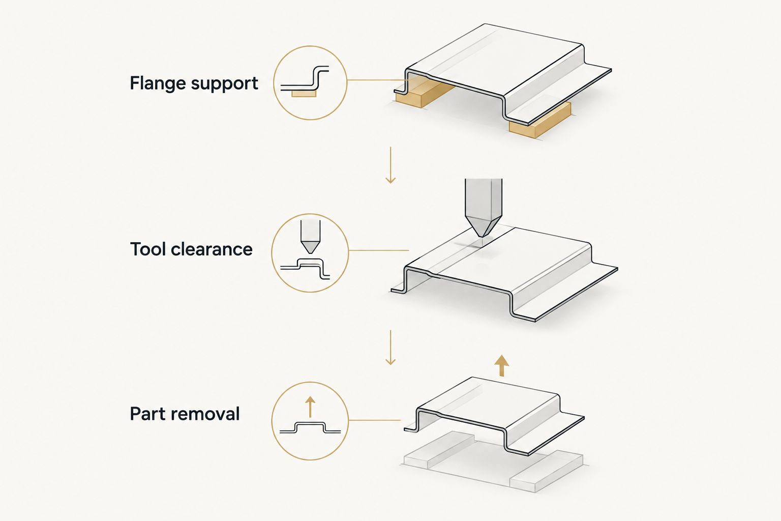
Map the bend sequence manually with part cross-sections before committing to a tooling arrangement. Show the part orientation at each operation, including already formed flanges. The critical clearance often occurs after the first bend, when the sheet no longer lies flat.
For your 2026 review, separate three checks: support during bending, clearance during motion and removal after forming. A short flange must remain adequately supported by the die arrangement. A return flange must clear the punch and holders throughout the stroke, not just at the final angle.
Use a physical layout or the machine's available simulation tools to review access. Simulation is useful for identifying interference, but its result depends on accurate tool, holder and machine geometry. Treat missing holder geometry as an unresolved check, not as empty space.
Complete the sequence review with:
- Flange support at each die opening.
- Clearance around formed returns and sidewalls.
- Punch, holder and machine interference checks.
- Backgauge contact and repositioning access.
- Finished-part removal and handling direction.
The sequence below organizes those checks without substituting for a dimensional review. Keep the support, clearance and removal decisions separate so a successful check in one area does not conceal a failure in another.
Select continuous or sectional tooling deliberately
Choose tool length and segmentation from the bend length and surrounding part geometry. Continuous tooling provides an uninterrupted working length. Sectional tooling lets you assemble a working length and leave clearance where formed walls or returns would otherwise interfere.
For enclosure box forming, review the position of every segment joint relative to the part. Confirm that the assembled set supports the intended bend and that the required end clearance exists. Do not assume that a collection of available segments produces the correct working length or a consistent installed height.
Sectional tooling also introduces setup responsibilities: segment identification, seating, alignment and handling. Verify how the holder retains the selected segments and how the manufacturer defines their permissible loads. If a segment is shortened, modified or used in a different arrangement, obtain an engineering review rather than carrying over the original assumption.
Check these length and segmentation details:
- Required working length for each bend.
- Segment lengths and assembled set arrangement.
- End clearance for sidewalls and returns.
- Segment seating and working-height consistency.
- Permissible loads for the selected arrangement.
Calculate loads for the actual forming operation
Use the machine or tooling manufacturer's approved calculation method with the specified material, thickness, bend length and die geometry. Identify whether the operation is air bending, bottoming, hemming or another forming process before applying a calculation. A load estimate for one process does not establish suitability for another.
Check the weakest rated element in the setup: machine, holder, punch or die. Review both total force and permissible force per unit length under the manufacturer's stated conditions. A short bend does not make a concentrated load acceptable merely because the machine has sufficient total capacity.
For hems, define the pre-bend geometry and the required finished condition. A nominal 180° closed hem and a teardrop hem need different geometric reviews; neither should be specified only as a folded edge. Verify closing loads separately from the pre-bend operation and account for the permitted surface contact.
Document the load review with:
- Forming process for each operation.
- Calculation method and material inputs.
- Bend length and selected die geometry.
- Machine, holder, punch and die limits.
- Separate limits for pre-bending and hem closing.
Validate the first article before releasing production
Treat your 2026 first-article review as an assembly check as well as a bending check. Measure the angle, radius and critical dimensions against the controlled drawing, then assess whether the formed part locates correctly against its mating components or approved inspection fixture.
Establish the inspection method before trial bending. Define where measurements are taken and how the part is supported during inspection; unsupported panels and inconsistent reference points can make results difficult to compare. Record any setup adjustment against the drawing revision and material used.
COVO's custom press brake tooling should be reviewed from the finished-part drawing, machine interface, material grade, thickness and required geometry. Tool selection is not production acceptance. Validate the actual tooling and process on your machine before releasing the setup for repeat work, and retain the accepted setup record with the part documentation.
Close the first-article review with:
- Finished angle, radius and flange measurements.
- Assembly fit and datum alignment.
- Surface marking and coating condition.
- Tooling identification and setup arrangement.
- Approved adjustments and acceptance record.
Compare die arrangements for enclosure work
For 2026 enclosure production, choose the arrangement that satisfies the part and machine constraints—not the arrangement with the broadest description. The options below have different strengths, and none eliminates interface, clearance or load verification.
| Option | Best for | Practical advantage | Key limitation |
|---|---|---|---|
| Continuous single-V die | Straight bends with unobstructed working length | Provides a continuous working profile | Tool length can obstruct formed sidewalls or complicate removal |
| Sectional single-V die set | Changing bend lengths and box geometries | Lets you configure working length and end clearance | Requires verified segment fit, seating and load limits |
| Multi-V die | Jobs requiring different openings within a compatible setup | Provides several selectable V-openings | Each selected opening still needs flange, radius, height and load checks |
| Dedicated hemming tooling | Specified flat or teardrop hems | Addresses the required pre-bend and closing geometry | Needs a separate closing-load and surface-contact review |
| COVO custom press brake tooling | Enclosure geometry not met by the available standard arrangement | Allows tooling specification from the part and machine inputs | Remains subject to engineering review and first-article validation |
Start with the tooling you already have if its documented geometry and ratings meet the requirement. Request a custom review when you can identify the specific conflict: unsupported flange, obstructed return, unsuitable working height or a forming profile that does not produce the specified geometry.
Common mistakes enclosure fabricators make
Selecting a V-opening without checking nearby cutouts
A nominal flange dimension does not describe all the available support when ventilation slots or other cutouts approach the bend. Review the actual blank and contact region, not just a simplified cross-section. Flag interrupted support for process review before releasing the tooling choice.
Treating a nominal angle as proof of assembly fit
A panel can reach its specified angle while its flange position or overall envelope remains outside the drawing requirement. Inspect the dimensions that locate doors, mounting faces and adjoining panels. Do not accept an angle-only first article for an assembly-controlled part.
Checking the final shape but not the intermediate bends
A finished enclosure model does not show every tool approach or handling position. Review the partially formed part at each operation. Include punch holders and backgauge access rather than checking only the punch tip and die opening.
Assuming a tooling-style name proves compatibility
AMADA-style, TRUMPF-style or another interface description is not a substitute for matched drawings. Verify the installed holder, retention features and working height. Keep the machine configuration in the tooling request, even when an earlier tool used the same general interface label.
Carrying an accepted setup across an unreviewed change
A different material grade, thickness, coating or drawing revision changes the review inputs. Identify which checks require repetition before reusing the setup. Preserve the accepted tooling record, but do not treat it as approval for an unspecified change.
FAQ
What's the best die for bending data center enclosure panels?
The best die is the arrangement that meets the specified flange geometry, radius, bend length and surface requirements within the machine and tooling limits. Review the matched punch, holder and bend sequence before selecting a single-V, multi-V or custom arrangement.
Are sectional dies better than continuous dies for enclosure boxes?
Sectional dies are better suited when the setup needs configurable working length or clearance around formed sidewalls. Continuous dies suit unobstructed straight bends, while sectional sets require additional segment seating, alignment and load checks.
How do I choose the V-opening for a short enclosure flange?
Choose the V-opening by checking flange support, required radius and permissible load together. A narrower opening changes the forming conditions and must be reviewed against the actual material and tool ratings.
Will the punch-tip radius determine the enclosure's inside radius?
The punch-tip radius alone does not determine the finished inside radius in air bending. Review the V-opening, material and bending process, then verify the resulting radius during first-article inspection.
What information should I send COVO for a custom tooling review?
Send COVO the finished-part drawing, machine interface details, material grade, thickness and required geometry. Include bend length, installed height, surface requirements and the proposed bend sequence so the tooling review addresses the complete setup.
Can I use the same dies for coated and uncoated enclosure panels?
Use the same dies only after verifying geometry, loads and acceptable surface contact for each material condition. Coating and protective media require their own marking and dimensional checks.
Do enclosure hems need a separate load calculation?
Enclosure hems need a load review specific to the closing operation. Verify the pre-bend, required hem geometry and rated closing loads rather than applying an air-bending calculation to the entire process.
One last thing
For your 2026 tooling release, add a finished-part removal sketch to the setup record. A bend sequence that reaches the correct geometry but traps the enclosure around the tooling is not an acceptable process. Approve the removal path alongside the forming path, before ordering tooling or releasing production.
Related guides
- Segmented press brake dies for box forming
- Press brake dies for thin-gauge sheet metal
- Sheet-metal hemming tools for aluminum panels
Open this COVO engineering guide · Browse press brake tooling · Request technical support